
The ROMS algorithms were
The actual nesting capabilities are not available yet. This will be released in Phase III in the near future
We are releasing this update at this time to allow the Users time to assimilate, test, and play with the new lateral boundary conditions structure. One of the advantages of the new design is the we can have different lateral boundary conditions for each active (temperature and salinity) and passive (inert, biology, sediment, etc) tracers. I highly recommend that you use the same lateral boundary conditions for temperature and salinity because they uniquely determine the density of the fluid via the equation of state for seawater.
This version is named ROMS 3.6. Once we have the full nesting in place and finish other important developments it will become ROMS 4.0. The current plan is to release ROMS 4.0 sometime this year
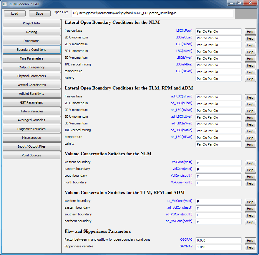
With the added complexity of nested grids, the ocean.in file can become very confusing and difficult to edit by hand. To help alleviate this problem we are developing a Graphical User Interface (GUI) to ocean.in. Since ROMS modelers use several different operating systems, we needed a solution that would be easy to maintain across the different platforms. We decided to use
What Is New:
- The lateral boundary conditions are specified by logical switches to facilitate applications with nested grids. It also allows setting different lateral boundary conditions between the nonlinear model and the adjoint/tangent models. In addition, we can have different boundary conditions between active and passive tracers. The LBC structure is allocated as:
where 1:4 are the numbered boundary edges, nLBCvar is the number of LBC state variables, and Ngrids is the number of nested grids. The boundary order is: 1=west, 2=south, 3=east, and 4=north. That is, anticlockwise starting at the western boundary.
Code: Select all
LBC(1:4, nLBCvar, Ngrids)
For example, the free-surface gradient boundary conditions are specified with the following switches:The structure is declared and allocated in mod_param.F as:Code: Select all
LBC(iwest, isFsur, ng) % gradient LBC(ieast, isFsur, ng) % gradient LBC(isouth, isFsur, ng) % gradient LBC(inorth, isFsur, ng) % gradientCode: Select all
TYPE T_LBC logical :: acquire ! process lateral boundary data logical :: Chapman logical :: clamped logical :: closed logical :: Flather logical :: gradient logical :: nested logical :: nudging logical :: periodic logical :: radiation logical :: reduced END TYPE T_LBC TYPE (T_LBC), allocatable :: LBC(:,:,:) TYPE (T_LBC), allocatable :: ad_LBC(:,:,:) TYPE (T_LBC), allocatable :: tl_LBC(:,:,:) - The lateral boundary conditions are now specified in the ocean.in input script. For example, User/External/ocean_cblast.in has:
Code: Select all
! Set lateral boundary conditions keyword. Notice that a value is expected ! for each boundary segment per nested grid for each state variable. ! ! Each tracer variable requires [1:4,1:NAT+NPT,Ngrids] values. Otherwise, ! [1:4,1:Ngrids] values are expected for other variables. The boundary ! order is: 1=west, 2=south, 3=east, and 4=north. That is, anticlockwise ! starting at the western boundary. ! ! The keyword is case insensitive and usually has three characters. However, ! it is possible to have compound keywords, if applicable. For example, the ! keyword "RadNud" implies radiation boundary condition with nudging. This ! combination is usually used in active/passive radiation conditions. ! ! Keyword Lateral Boundary Condition Type ! ! Cha Chapman ! Cla Clamped ! Clo Closed ! Fla Flather _____N_____ j=Mm ! Gra Gradient | 4 | ! Nes Nested | | ! Nud Nudging 1 W E 3 ! Per Periodic | | ! Rad Radiation |_____S_____| ! Red Reduced Physics 2 j=1 ! i=1 i=Lm ! W S E N ! e o a o ! s u s r ! t t t t ! h h ! ! 1 2 3 4 LBC(isFsur) == Cha Cha Cha Cha ! free-surface LBC(isUbar) == Fla Fla Fla Fla ! 2D U-momentum LBC(isVbar) == Fla Fla Fla Fla ! 2D V-momentum LBC(isUvel) == RadNud RadNud RadNud RadNud ! 3D U-momentum LBC(isVvel) == RadNud RadNud RadNud RadNud ! 3D V-momentum LBC(isMtke) == Gra Gra Gra Gra ! mixing TKE LBC(isTvar) == RadNud RadNud RadNud RadNud \ ! temperature RadNud RadNud RadNud RadNud ! salinity ! Adjoint-based algorithms can have different lateral boundary ! conditions keywords. ad_LBC(isFsur) == Cha Cha Cha Cha ! free-surface ad_LBC(isUbar) == Fla Fla Fla Fla ! 2D U-momentum ad_LBC(isVbar) == Fla Fla Fla Fla ! 2D U-momentum ad_LBC(isUvel) == RadNud RadNud RadNud RadNud ! 3D U-momentum ad_LBC(isVvel) == RadNud RadNud RadNud RadNud ! 3D V-momentum ad_LBC(isMtke) == Gra Gra Gra Gra ! mixing TKE ad_LBC(isTvar) == RadNud RadNud RadNud RadNud \ ! temperature RadNud RadNud RadNud RadNud ! salinity ! Set lateral open boundary edge volume conservation switch for ! nonlinear model and adjoint-based algorithms. Usually activated ! with radiation boundary conditions to enforce global mass ! conservation, except if tidal forcing enabled. [1:Ngrids]. VolCons(west) == F ! western boundary VolCons(east) == F ! eastern boundary VolCons(south) == F ! southern boundary VolCons(north) == F ! northern boundary ad_VolCons(west) == F ! western boundary ad_VolCons(east) == F ! eastern boundary ad_VolCons(south) == F ! southern boundary ad_VolCons(north) == F ! northern boundary - Notice that the keyword is case insensitive and usually has three characters. It contains the first three characters of the field in the LBC structure (Fla => % Flather). However, it is possible to have compound keywords, if applicable. For example, the keyword RadNud implies radiation boundary condition with nudging. This combination is usually used in active/passive radiation conditions. This design is very generic and will allow us to implement new or expand lateral boundary conditions in the future.
- The location of the lateral boundary conditions section in the ocean.in input script is very important and must always be immediately following the specification of the domain decomposition parameters:
This is because the periodic boundary switches are needed for the allocation of several ROMS modules early during the processing of ocean.in.
Code: Select all
! Domain decomposition parameters for serial, distributed-memory or ! shared-memory configurations used to determine tile horizontal range ! indices (Istr,Iend) and (Jstr,Jend), [1:Ngrids]. NtileI == 1 ! I-direction partition NtileJ == 1 ! J-direction partition - If your lateral boundary conditions are periodic, all the variables in such periodic direction must be set to periodic (Per keyword). I highly recommend that you set the same type of lateral boundary conditions for 2D momentum components (ubar, vbar). Similarly, use the same lateral boundary conditions for 3D momentum components (u, v).
- Notice all that the volume conservation options used in radiation conditions,VolCons(1:4,ng), are also set in ocean.in. The volume conservations are usually activated with radiation boundary conditions to enforce global mass conservation, except if tidal forcing enabled.
- Similarly, the lateral boundary conditions for biological and sediment tracers are set in their respective input parameter scripts. For example, for the 11 component Nemuro model we have in ROMS/External/nemuro.in:
Notice that the ROMS input line continuation symbol (\) is used after every component is specified, except the last one (idbio(11), opal). The comments after the continuation symbol are ignored in ROMS.
Code: Select all
! W S E N ! e o a o ! s u s r ! t t t t ! h h ! ! 1 2 3 4 LBC(isTvar) == Per Clo Per Clo \ ! idbio( 1), nanophytoplankton Per Clo Per Clo \ ! idbio( 2), diatom Per Clo Per Clo \ ! idbio( 3), microzooplankton Per Clo Per Clo \ ! idbio( 4), mesozooplankton Per Clo Per Clo \ ! idbio( 5), Pzooplankton Per Clo Per Clo \ ! idbio( 6), NO3 Per Clo Per Clo \ ! idbio( 7), NH4 Per Clo Per Clo \ ! idbio( 8), PON Per Clo Per Clo \ ! idbio( 9), DON Per Clo Per Clo \ ! idbio(10), SiOH4 Per Clo Per Clo ! idbio(11), opal - Alternatively, you can specify the passive tracers lateral boundary conditions in a compact form. For example, in ROMS/External/ecosim.in for the EcoSim bio-optical model (61 passive tracers) we have:
In this case, ROMS will assign the same values as the first entry, idbio(1), for all 61 passive tracers. This is the same strategy that it is used in other input parameters when they are not specified. The compact form is very handy in applications with a lot of passive tracers. However, it should not be used if you desire different lateral boundary condition for various tracers. The order of the entries is very important and should follow the exact same order as in the model tracer array, t(:,:,:,:,itrc).
Code: Select all
! W S E N ! e o a o ! s u s r ! t t t t ! h h ! ! 1 2 3 4 LBC(isTvar) == Per Clo Per Clo ! idbio(:), compact - In sediment applications, both cohesive and non-cohesive sediment concentrations lateral boundary conditions are specified together. For Example, we may have in sediment.in:
That is, we specify the cohesive sediments (mud) first, if any. Then, we specify next the non-cohesive sediments (sand), if any. We need to follow the same order of the sediment concentration tracers as in t(:,:,:,:,itrc).
Code: Select all
! W S E N ! e o a o ! s u s r ! t t t t ! h h ! ! 1 2 3 4 LBC(isTvar) == Gra Clo Cla Clo \ ! idsed(1), mud_01 Gra Clo Cla Clo \ ! idsed(2), mud_02 Gra Clo Cla Clo \ ! idsed(3), sand_01 Gra Clo Cla Clo \ ! idsed(4), sand_02 Gra Clo Cla Clo ! idsed(5), sand_03 - In nesting applications, which will be released in Phase III, you need to specify the lateral boundary conditions for every grid. For example, we can have:
Here, grid 1 is the parent and coarser whereas grid 2 is the child and finer in an application with grid refinement.
Code: Select all
! W S E N ! e o a o ! s u s r ! t t t t ! h h ! ! 1 2 3 4 LBC(isFsur) == Clo Cha Cha Cha \ ! free-surface, grid 1 Nes Nes Nes Nes ! free-surface, grid 2 LBC(isUbar) == Clo Fla Fla Fla \ ! 2D U-momentum, grid 1 Nes Nes Nes Nes ! 2D U-momentum, grid 2 LBC(isVbar) == Clo Fla Fla Fla \ ! 2D V-momentum, grid 1 Nes Nes Nes Nes ! 2D V-momentum, grid 2 LBC(isUvel) == Clo Cla Cla Cla \ ! 3D U-momentum, grid 1 Nes Nes Nes Nes ! 3D U-momentum, grid 2 LBC(isVvel) == Clo Cla Cla Cla \ ! 3D V-momentum, grid 1 Nes Nes Nes Nes ! 3D V-momentum, grid 2 LBC(isMtke) == Clo Gra Gra Gra \ ! mixing TKE, grid 1 Nes Nes Nes Nes ! mixing TKE, grid 2 LBC(isTvar) == Clo Cla Cla Cla \ ! temperature, grid 1 Clo Cla Cla Cla \ ! salinity, grid 1 Nes Nes Nes Nes \ ! temperature, grid 2 Nes Nes Nes Nes ! salinity, grid 2 - Notice that you may want to specify different lateral boundary conditions for adjoint-based applications. If so, we use the same values in the TLM, RPM, and ADM to preserve the symmetry of the linearized model state operator. This is crucial. The values in the ad_LBC and tl_LBC structures must be identical.
In 4D-Var data assimilation, this will allows us to have different lateral boundary conditions in the background nonlinear trajectory (outer loop) and adjoint and tangent linear models (inner loop). For example, in some applications is convenient to use radiation conditions in open boundaries in the nonlinear model. However, it is very difficult to use radiation conditions in the adjoint and tangent linear model because of stability and cumbersome storage of the inflow/outflow variables at every time step. We still need to think more about what to do when adjusting the lateral boundary condition (ADJUST_BOUNDARY) if different values are used for LBC and ad_LBC.
Code: Select all
! Adjoint-based algorithms can have different lateral boundary ! conditions keywords. ad_LBC(isFsur) == Clo Cha Cha Cha ! free-surface ad_LBC(isUbar) == Clo Fla Fla Fla ! 2D U-momentum ad_LBC(isVbar) == Clo Fla Fla Fla ! 2D U-momentum ad_LBC(isUvel) == Clo Cla Cla Cla ! 3D U-momentum ad_LBC(isVvel) == Clo Cla Cla Cla ! 3D V-momentum ad_LBC(isMtke) == Clo Gra Gra Gra ! mixing TKE ad_LBC(isTvar) == Clo Cla Cla Cla \ ! temperature Clo Cla Cla Cla ! salinity - I highly recommend you that you always check the standard output file or the global header (NLM_LBC attribute) in the output NetCDF files to confirm that your applications have the expected lateral boundary conditions.
- Three new routines are provided to process the lateral boundary conditions structure in ROMS/Utility/lbc.F:
- lbc_getatt: If restart, this routine reads lateral boundary conditions keywords strings from restart NetCDF file global attribute (NLM_LBC). Then, it checks those values against the ones provided in input script for consistency. This routine is called from ROMS/Utility/get_state.F.
- lbc_putatt: This routine writes lateral boundary conditions keyword strings into the specified output NetCDF files' global attribute. It is call from ROMS/Utility/def_info.F. For Example, a ncdump of ocean_his.nc will print:
Notice that a Line Feed (LF) symbol is added at the end of each entry (\n) for readability. This is done in Fortran by using CHAR(10). Where 10 is the decimal value for LF control character in the
Code: Select all
:NLM_LBC = "\n", "EDGE: WEST SOUTH EAST NORTH \n", "zeta: Per Clo Per Clo \n", "ubar: Per Clo Per Clo \n", "vbar: Per Clo Per Clo \n", "u: Per Clo Per Clo \n", "v: Per Clo Per Clo \n", "temp: Per Clo Per Clo \n", "salt: Per Clo Per Clo \n", "nanophytoplankton: Per Clo Per Clo \n", "diatom: Per Clo Per Clo \n", "microzooplankton: Per Clo Per Clo \n", "mesozooplankton: Per Clo Per Clo \n", "Pzooplankton: Per Clo Per Clo \n", "NO3: Per Clo Per Clo \n", "NH4: Per Clo Per Clo \n", "PON: Per Clo Per Clo \n", "DON: Per Clo Per Clo \n", "SiOH4: Per Clo Per Clo \n", "opal: Per Clo Per Clo" ; standard ASCII character set.
 - lbc_report: This routine reports to standard output lateral boundary conditions structure value for requested state variables. It is called from inp_par.F.
- The routine ROMS/Utilily/inp_par.F is split into various files so it is more manageable now. This routine was getting too big. The routines that read the parameters from the input scripts are now stand alone and can be found in ROMS/Utility:
- read_asspar.F: reads and reports data assimilation input parameters (s4dvar.in).
- read_biopar.F: reads and reports biological model input parameters (bio_Fennel.in, ecosim.in, nemuro.in, npzd_Franks.in, npzd_Powell.in, npzd_iron.in).
- read_couplepar.F: reads and reports multiple model coupling input parameters (coupling.in).
- read_fltpar.F: reads and reports floats trajectories input parameters (floats.in).
- read_phypar.F: reads and reports physical model input parameters (ocean.in). This routine is still too long and we may get optimization warnings from the ifort compiler. These warnings can be ignored because there is nothing to optimize and is called only during initialization.
- read_sedpar.F: reads and reports sediment model input parameters (sediment.in).
- read_stapar.F: reads and reports station input parameters (stations.in).
- A new function load_lbc is added to inp_par.F to process the lateral boundary conditions keywords from input script files. This function is called from routines read_BioPar, read_PhyPar, and read_SedPar.
- If restart, the NLM_LBC global attribute (described above) in the restart NetCDF file is checked to guarantee identical lateral boundary conditions set-up. This is done in get_state.F during the call to routine get_lbc. This implies that the restart file has to be generated by ROMS version 3.6 or higher. It will not work with restart files generated with old versions of ROMS. This global attribute is new to ROMS 3.6. In such cases, use the restart file as initial conditions instead of restart or activate new C-preprocessing option NO_LBC_ATT to avoid checking the NLM_LBC global attribute. If activating NO_LBC_ATT, it is your responsibility to check the lateral boundary conditions used to create the old restart file against those in your input script(s) for consistency.
- Backward compatibility with previous versions of ROMS is a little tricky bit but possible. After all, we are just changing C-preprocessing directives with Fortran logical switches. There are no changes to the computational kernels but changes in the flow of the computations. All the lateral boundary conditions are available after compiling (for instance, see Build/zetabc_im.f90). This can be both an advantage or a disadvantage. It is advantageous because we do not need to recompile the entire code when the lateral boundary conditions are changed. It also greatly facilitates nesting with simple logic instead of cumbersome and additional C-preprocessing options. It facilitates different lateral boundary conditions for some or all tracer fields. However, it is disadvantageous in the sense that we can no longer easily see which lateral boundary conditions were activated. We need to inspect carefully the standard output and NetCDF file global attributes.
All the C-preprocessing lateral boundary conditions options are removed from the svn distributed code. As such, any CPP option that you may have in your application header file will be ignored. However, it is very dangerous to have them if you have customized the code or use any customized analytical routines from ROMS/Functionals or User/Functionals. Therefore, I highly recommend that you remove them from your application header file and use the build script instead. I am providing examples of how this is done in the test repository. For example, in the INLET_TEST case (test/inlet_test/build.sh) we have:
Notice the local environmental variable BACK_COMPATIBILITY which allows you to set the lateral boundary conditions C-preprocessing options for backward compatibility with older versions of the code. You can also modify the build script to use the old/new header files. For example, you may have:Code: Select all
# Set tunable CPP options. # # Sometimes it is desirable to activate one or more CPP options to run # different variants of the same application without modifying its header # file. If this is the case, specify each options here using the -D syntax. # Notice also that you need to use shell's quoting syntax to enclose the # definition. Both single or double quotes work. For example, # # setenv MY_CPP_FLAGS "-DAVERAGES" # setenv MY_CPP_FLAGS "${MY_CPP_FLAGS} -DDEBUGGING" # # can be use to write time-averaged fields. Notice that you can have as # many definitions as you want by appending values. setenv MY_CPP_FLAGS "-DSWAN_COUPLING" setenv MY_CPP_FLAGS "${MY_CPP_FLAGS} -DMCT_LIB" #setenv MY_CPP_FLAGS "${MY_CPP_FLAGS} -DDEBUGGING" #setenv MY_CPP_FLAGS "${MY_CPP_FLAGS} -DOUT_DOUBLE" #setenv MY_CPP_FLAGS "${MY_CPP_FLAGS} -DPOSITIVE_ZERO" #setenv MY_CPP_FLAGS "${MY_CPP_FLAGS} -DUV_LOGDRAG" #setenv MY_CPP_FLAGS "${MY_CPP_FLAGS} -DUV_QDRAG" #setenv MY_CPP_FLAGS "${MY_CPP_FLAGS} -DMB_BBL" #setenv MY_CPP_FLAGS "${MY_CPP_FLAGS} -DSG_BBL" setenv MY_CPP_FLAGS "${MY_CPP_FLAGS} -DSSW_BBL" setenv MY_CPP_FLAGS "${MY_CPP_FLAGS} -DNEARSHORE_MELLOR05" #setenv MY_CPP_FLAGS "${MY_CPP_FLAGS} -DBEDLOAD_SOULSBY" #setenv MY_CPP_FLAGS "${MY_CPP_FLAGS} -DBEDLOAD_MPM" # Set deprecated lateral boundary conditions CPP flags for backward # compatibility with older versions of the code. setenv BACK_COMPATIBILITY on # needed for ROMS 3.4 or older if ($?BACK_COMPATIBILITY) then setenv MY_CPP_FLAGS "${MY_CPP_FLAGS} -DSOUTHERN_WALL" setenv MY_CPP_FLAGS "${MY_CPP_FLAGS} -DNORTH_FSGRADIENT" setenv MY_CPP_FLAGS "${MY_CPP_FLAGS} -DNORTH_M2REDUCED" setenv MY_CPP_FLAGS "${MY_CPP_FLAGS} -DFSOBC_REDUCED" setenv MY_CPP_FLAGS "${MY_CPP_FLAGS} -DNORTH_M3GRADIENT" setenv MY_CPP_FLAGS "${MY_CPP_FLAGS} -DNORTH_TGRADIENT" setenv MY_CPP_FLAGS "${MY_CPP_FLAGS} -DWEST_FSGRADIENT" setenv MY_CPP_FLAGS "${MY_CPP_FLAGS} -DWEST_M2GRADIENT" setenv MY_CPP_FLAGS "${MY_CPP_FLAGS} -DWEST_M3GRADIENT" setenv MY_CPP_FLAGS "${MY_CPP_FLAGS} -DWEST_TGRADIENT" setenv MY_CPP_FLAGS "${MY_CPP_FLAGS} -DEAST_FSGRADIENT" setenv MY_CPP_FLAGS "${MY_CPP_FLAGS} -DEAST_M2GRADIENT" setenv MY_CPP_FLAGS "${MY_CPP_FLAGS} -DEAST_M3GRADIENT" setenv MY_CPP_FLAGS "${MY_CPP_FLAGS} -DEAST_TGRADIENT" endifWell, I told you it was a little bit tricky. But I think that you can handle itCode: Select all
# If applicable, use the MY_ANALYTICAL_DIR directory to place your
# customized biology model header file (like fennel.h, nemuro.h, ecosim.h,
# etc).

 setenv MY_HEADER_DIR       ${MY_PROJECT_DIR}

if (! $?BACK_COMPATIBILITY) then
  setenv MY_ANALYTICAL_DIR   ${MY_PROJECT_DIR}/Functionals_new
else
  setenv MY_ANALYTICAL_DIR   ${MY_PROJECT_DIR}/Functionals_old
endif
- A table of all the C-preprocessing options that were removed and the equivalent logical switch can be found in the following WikiROMS page. I advise you to check this information.
- Two new logical switches ConposedGrid(ng) and RefinedGrid(ng) are defined, allocated and initialized in mod_scalars.F to access or not sections of code relevant to composed and refined grids, respectively.
- Throughout the entire code the EW_PERIODIC directive is replaced with EWperiodic(ng) and NS_PERIODIC directive is replaced with NSperiodic(ng). Both periodic logical switches are declared, allocated, and initialized in ROMS/Modules/mod_scalars.F. Use the following conversions:
Code: Select all
Use IF (EWperiodic(ng)) THEN ... END IF instead of #ifdef EW_PERIODIC or #if defined EW_PERIODIC ... ... #endif #endif ________________________________________________________________________ Use IF (NSperiodic(ng)) THEN ... END IF instead of #ifdef NS_PERIODIC or #if defined NS_PERIODIC ... ... #endif #endif ________________________________________________________________________ Use IF (.not.EWperiodic(ng)) THEN ... END IF instead of #ifndef EW_PERIODIC or #if !defined EW_PERIODIC ... ... #endif #endif ________________________________________________________________________ Use IF (.not.NSperiodic(ng)) THEN ... END IF instead of #ifndef NS_PERIODIC or #if !defined NS_PERIODIC ... ... #endif #endif ________________________________________________________________________ Use IF (EWperiodic(ng).and.NSperiodic(ng)) THEN ... END IF instead of #if defined EW_PERIODIC && defined NS_PERIODIC ... #endif ________________________________________________________________________ Use IF (EWperiodic(ng).or.NSperiodic(ng)) THEN ... END IF instead of #if defined EW_PERIODIC || defined NS_PERIODIC ... #endif ________________________________________________________________________ Use IF (.not.(EWperiodic(ng).or.NSperiodic(ng))) THEN ... END IF instead of #if !defined EW_PERIODIC && !defined NS_PERIODIC ... #endif - Remove the following declaration of local switches from all your customized routines:
This is usually found in the local variable declarations section at the beginning of each routine. This is only needed in distributed-memory applications.
Code: Select all
#ifdef DISTRIBUTE # ifdef EW_PERIODIC logical :: EWperiodic=.TRUE. # else logical :: EWperiodic=.FALSE. # endif # ifdef NS_PERIODIC logical :: NSperiodic=.TRUE. # else logical :: NSperiodic=.FALSE. # endif #endif - In distributed memory, the above declaration is not needed since we already have the global EWperiodic(ng) and NSperiodic(ng) logical switches.
That is, (ng) is added to both the EWperiodic and NSperiodic variable arguments. Notice that if you do not remove the local declaration mentioned in previous item, you will get an error from the compiler because EWperiodic and NSperiodic has been already declared in module mod_scalars and are not longer scalars but 1D arrays, 1:Ngrids. This was done intentionally...
Code: Select all
We now use

#ifdef DISTRIBUTE
      CALL mp_exchange2d (ng, tile, model, 1,                           &
     &                    LBi, UBi, LBj, UBj,                           &
     &                    NghostPoints,                                 &
     &                    EWperiodic(ng), NSperiodic(ng),               &
     &                    Pair)
#endif

instead of

#ifdef DISTRIBUTE
      CALL mp_exchange2d (ng, tile, model, 1,                           &
     &                    LBi, UBi, LBj, UBj,                           &
     &                    NghostPoints, EWperiodic, NSperiodic,         &
     &                    Pair)
#endif
In some routines you may have to include module mod_scalars to have access to EWperiodic(ng) and NSperiodic(ng). Otherwise, the compiler will give you an error. You need to add:Code: Select all
USE mod_scalars - You always need to include the periodic routines module. For example,
Code: Select all
use USE exchange_2d_mod, ONLY : exchange_r2d_tile instead of #if defined EW_PERIODIC || defined NS_PERIODIC USE exchange_2d_mod, ONLY : exchange_r2d_tile #endif - In order to use ROMS Version 3.6 or higher, every user needs to update all their customized analytical header files (ana_*.h) to replace the periodic lateral boundary C-preprocessing options EW_PERIODIC and NS_PERIODIC with the logical switches EWperiodic(ng) and NSperiodic(ng), respectively, as shown above. This is very easy
 However, the files ana_hmixcoef.h and ana_nudgcoef.h are more elaborated. The routine in ana_hmixcoef.h is used to set horizontal mixing coefficients in the sponge areas next to the open boundaries whereas ana_nudgcoef.h is used to set nudging coefficients for the interior and boundary points. Both routines have a generic section at the bottom after the following comment:
Please use the new version of the generic code. I recommend that you start with the new version of these routines and add the code needed by your application.
However, the files ana_hmixcoef.h and ana_nudgcoef.h are more elaborated. The routine in ana_hmixcoef.h is used to set horizontal mixing coefficients in the sponge areas next to the open boundaries whereas ana_nudgcoef.h is used to set nudging coefficients for the interior and boundary points. Both routines have a generic section at the bottom after the following comment:
Please use the new version of the generic code. I recommend that you start with the new version of these routines and add the code needed by your application.Code: Select all
!! WARNING: This section is generic for all applications. Please do not !! change the code below. !! ... - Notice that the internal C-preprocessing option NUDGING_COEF, defined previously in globaldefs.h, is eliminated and replaced with logical switch NudgingCoeff(ng). This switch is used in ana_nudgcoef.h.
- Also, the internal C-preprocessing option OBC_DATA, defined previously in globaldefs.h, is eliminated and replaced with logical switch ObcData(ng). This switch is activated internally in read_phypar.F to process lateral boundary conditions NetCDF file.
- Finally if you are not sure of what to do, compare an old and new version of the file in question. Use tagged Version 3.5 as the old version and the current trunk revision as the new version.